Difference between revisions of "RGB LED"
Jump to navigation
Jump to search
| Line 1: | Line 1: | ||
= Description = | = Description = | ||
A regular RGB LED is basically 3 LEDs (one red, one green, one blue) in parallel. This is not a smart LED, for smart LEDs see [[LED Ring NeoPixel]] | A regular RGB LED is basically 3 LEDs (one red, one green, one blue) in parallel. This is not a smart LED, for smart LEDs see [[LED Ring NeoPixel]] | ||
| + | |||
| + | |||
| + | = How to connect it electrically = | ||
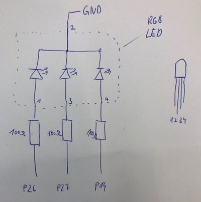
| + | The RGB LED is connected like 3 paralell LEDs. It is important that you need one resistor for each color! The resistor goes before the LED and not onto the common ground. | ||
[[File:RgbIMG 9775.jpg|400px]] | [[File:RgbIMG 9775.jpg|400px]] | ||
| − | |||
| − | |||
| − | |||
= How to control it in MicroPython = | = How to control it in MicroPython = | ||
Revision as of 23:36, 19 August 2020
Contents
Description
A regular RGB LED is basically 3 LEDs (one red, one green, one blue) in parallel. This is not a smart LED, for smart LEDs see LED Ring NeoPixel
How to connect it electrically
The RGB LED is connected like 3 paralell LEDs. It is important that you need one resistor for each color! The resistor goes before the LED and not onto the common ground.
How to control it in MicroPython
1 # todo
2 # code goes here
A small Program in MicroPython
1 # todo
2 # code goes here
text
image(s)
Related Tutorial Videos
In this part of the tutorial, we show how to connect an RGB-LED and programming it with Micropython. We first look at what an RGB LED is by building one with 3 separate LEDs. We then look at switching it on and off and how to set the color using the duty cycle in the PWM output.
Background
text
image(s)
