Team4 gyro and acceleration sensor
MPU-6050 gyroscope and acceleration sensor
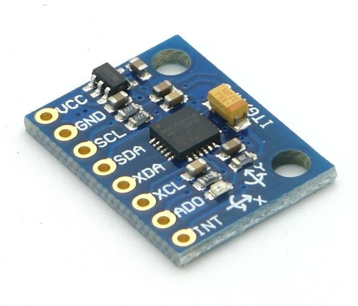
The MPU-6050 is a MEMS-based sensorchip for motion tracking built into the GY-521 breakoutboard
Thanks to its 3-axis gyroscope and 3-axis acceleration sensors, it can recognize 6 DOF (degrees of freedom) simultaneously.
That means it can measure its orientation/rotation and acceleration in a 3D space (6 DOF).
In addition to that, the environment temperature can be measured as well.
GY521 - MPU 6050
Core Features
   * Chip: MPU-6050 (InvenSense)
   * 16-Bit AD-Converter
   * Acceleration sensor range: ±2, ±4, ±8, ±16g
   * Gyro range: ±250°, 500°, 1000°, 2000°/s
   * Voltage range: 3,3V - 5V
Technical Specifications
The module has its own I²C bus, which allows for an easy connection with microcontrollers such as the ESP32. Ideally, 5V should be used to guarantee a sufficient power supply. Arrows on the board indicate the x and y axis for convenient usage.
The built in Digital motion Prozessor (DMP) processes complex algorithms directly on the board, for example to procces the raw sensor data to stable position data.
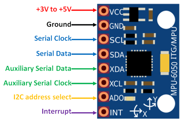
Pinout
- VCC
- First one is the VCC Pin, which is used to power the sensor, 3V - 5V can be applied
- GND
- Ground Pin, which should be connected to one of the microcontrollers ground pins
- SCL
- Serial Clock (I²C). Connected to an SCL-Pin of the microcontroller, a clock pulse will be emitted which is used in I²C communication
- The clock source is provided by the microcontroller
- SDA
- Serial Data (I²C). SDA is used to transfer data to a microcontroller, connected to the microcontrollers SDA-Pin
- XDA
- Auxiliary Serial Data. Can be used to connect external I²C modules, like a magnetometer
- The use of it is totally optional.(Not covered in this wikipage)
- XCL
- Auxiliary Serial Clock. Is used for communication with external I²C modules
- The use of it is totally optional.(Not covered in this wikipage)
- AD0
- Address Select Pin. Its a slave address. If you connect more than one MPU6050 with your microcontroller,
- the I²C bus of the microcontroller can distinguish the modules thanks to the unique address
- low -> 0x68; high 0x69
- INT
- Interrupt. Which is an interrupt digital output pin
- Is used to give the microcontroller indication that data is available to read. Use is optional
Advantages / Disadvantages
Advantages
- Easy to use
- Orientation indicators
- Small and light
- DMP
Disadvantages
- Some GY521 use 2,2kΩ, which can be a problem if other sonsormodules are used too. A additional extern pullup resistor can help in these cases
- Some GY521 have a wrong or damaged capacitor which can lead to noise in the sensordata
Get it to Work
This Step-by-Step Guide shows how to connect the NodeMCU ESP32 with the GY521 - MPU6050 in the Arduino IDE.
IDE Setup
- Install latest Arduino IDE
- Update/install the CP210X USB-UART driver
- Setup ESP32 in Arduino IDE
- Open Arduino IDE
- File>Preferences enter in "Additional Boards Manager URLs" the following URL - "https://dl.espressif.com/dl/package_esp32_index.json"
- Click OK
- Tools>Board>Boards Manager...
- Install "esp32" by espressif Systems
- Click Tools>Board>ESP32 DEV Module
(Your choice depends on the Board you are using. For NodeMCU ESP32 choose "ESP32 DEV Module") - Tools>Manage Libraries search for"Adafruit mpu6050"
- Install the Library and all its dependencies
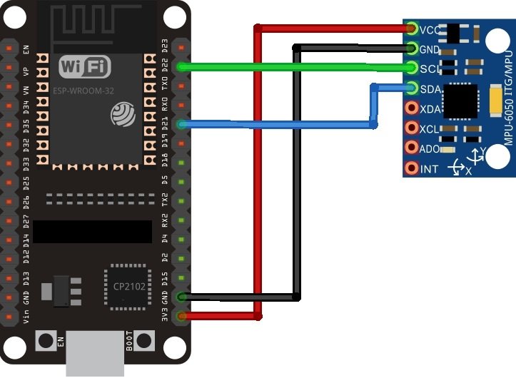
Wireing
Wireing Schematic Connect like following (GY521(MPU6050) -> ESP32):
- VCC -> 3V3
- GND -> GND
- SCL -> D22 (GPIO22 I²C SCL)
- SDA -> D21 (GPIO21 I²C SDA)
ESP32 Setup
- Connect your ESP32 via USB to your machine
- In the IDE make sure you selected the right Port.
Tools>Port>"Port of the connected ESP32" - In Arduino IDE File>Examples>Adafruit MPU6050>plotter
- In the newly opened window with the Plotter-Code, click "Upload" and hold down the "Boot" button on the ESP32
- when the upload is completed, press the reset button "EN" on your ESP32
Data Readings
- Tools>Serial Monitor -> this will show you the Plotter-Code output.
- Tools>Serial Plotter -> this will show you the outputdata plotted as a Graph.
Other IDE's
You can connect the GY251(MPU6050) in many ways with ESP32.
So here is a more generic guide with mycrophython.
- Create a new file on your machine
- Copy the following code and paste it in your new file -> mpu6050.py(Mycropython I²C API for ESP32 and ESP8266)
- Save the file as "mpu6050.py"
- Now upload the file to your ESP32
- Create a new file named main.py
- Copy the Code Example below in your "main.py" file
- Upload "main.py" to your ESP32
- Read the output in your preferred IDE's shell
Code Example
from machine import I2C
from machine import Pin
from machine import sleep
import mpu6050

i2c = I2C(scl=Pin(22), sda=Pin(21))     #initializing the I2C method for ESP32
#i2c = I2C(scl=Pin(5), sda=Pin(4))       #initializing the I2C method for ESP8266
mpu= mpu6050.accel(i2c)

while True:
 mpu.get_values()
 print(mpu.get_values())
 sleep(500)
Video