Tutorial Analog IN: Difference between revisions
| Line 6: | Line 6: | ||
* you understand how to build a voltage divider to read a sensor value from a changing resistor | * you understand how to build a voltage divider to read a sensor value from a changing resistor | ||
* you can connect a Potentiometer, a slider, and a [[LDR]] to the ESP32/ESP8266 and read the value | * you can connect a Potentiometer, a slider, and a [[LDR]] to the ESP32/ESP8266 and read the value | ||
== Related Components == | |||
The components are related to the [[LMUBox]]. For more components, see the [[Hardware List]. Many of the pages on actuators and sensors include additional examples. | |||
=== Microcontroller === | |||
* [[ESP32 Web Kit]] with integrated OLED Display from Heltec | |||
* [[ESP8266 ESP-12F]] NodeMCU Module from AZDelivery | |||
=== Sensors (and physical controllers) === | |||
* [[LDR]] Light dependend resistor | |||
* [[Potentiometer]] short Poti, changeable resistors as slider and knobs | |||
* [[Analog Joystick]] | |||
= Instructional Videos = | = Instructional Videos = | ||
Revision as of 14:15, 31 August 2020
Analog Input with MicroPyton and ESP32/ESP8266
In this part of the tutorial, we demonstrate how to read in an analog value using MicroPyton on ESP32/ESP8266. We also show how we can use the analog input to measure a changing resistor. This includes looking at the voltage range that can be measured the resolution of the analog-digital converter (ADC).
Success criteria
- you can read in an analog value from the python prompt
- you understand how to build a voltage divider to read a sensor value from a changing resistor
- you can connect a Potentiometer, a slider, and a LDR to the ESP32/ESP8266 and read the value
Related Components
The components are related to the LMUBox. For more components, see the [[Hardware List]. Many of the pages on actuators and sensors include additional examples.
Microcontroller
- ESP32 Web Kit with integrated OLED Display from Heltec
- ESP8266 ESP-12F NodeMCU Module from AZDelivery
Sensors (and physical controllers)
- LDR Light dependend resistor
- Potentiometer short Poti, changeable resistors as slider and knobs
- Analog Joystick
Instructional Videos
The videos are a first test... the ones marked with ** will be replaced over the next months with new versions.
Analog Input - ADC - connecting a variable resistor **
In this video on youtube (46:23) we show how to connect to read in an analog value with MicroPython. We also show how a sensor that is based on a changing resistance can be connected using a voltage divider: https://youtu.be/gjj5KyK2qGI
Schematics and Code Example
Schematics for connecting to ESP32
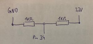
This should divide the voltage by half as both resistors are the same - you should read a value of about 2000 (assuming 12Bit resolution with a range of 0-4096)
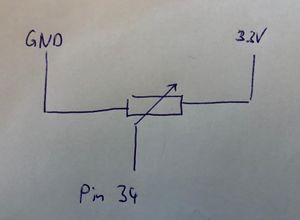
Connecting the potentiometer (poti) or slider. The value you read is dependent on where your poti or slider stands.
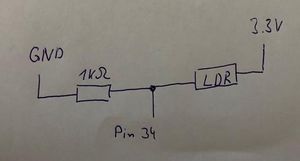
Connecting the light dependent resistor (LDR). The value you read is dependent on how bright it is.
Code Example
This makes Pin 34 an analog input and set it to 12 bit. It reads the analog value every second and print it to the console-
#Example usage for ESP32
from machine import Pin, ADC
from time import sleep

analogPin = ADC(Pin(34))
analogPin.atten(ADC.ATTN_11DB)

while True:
  analogVal = analogPin.read()
  print(analogVal)
  sleep(1)

